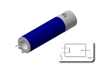
- Classical technical design for high power
- HT polarity: (-) minus
- Anode at ground potential
- Water cooling
- Filament at high potential
- X-ray window near to focal spot
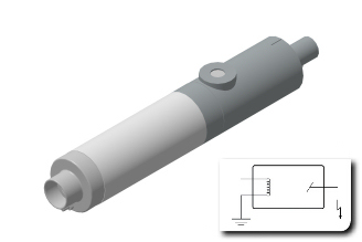
- Low power X-ray tube design
- HT polarity: (+) plus
- Anode at high potential
- Cooling through electrically insulating
- material (e. g. oil or ceramic)
- Filament at ground potential
- X-ray window positioned outside of the HT field
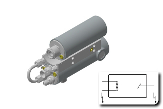
- Preferable designed for higher voltages
- HT polarity: (-) minus and (+) plus
- Anode and cathode at high potential
- Cooling through electrical insulating
- material (oil or ceramic)
- Filament at high potential
- X-ray window positioned outside of the HT field
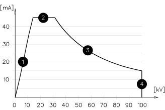
- Max tube power at lower kV
- Max. mA limited by the power supply only
- Tube power
- Max. nominal high tension
The fieldstrength is not high enough to accelrate the entire electron cloud around the filament.
Therefore the filament needs to be heated at higher temperature and is limiting the tube power by its lifetime.
The max. tube power is limited by the max. specific load on the focal spot. This varies with the target material
The max. accelration voltage is based on a risk assessment.
Following will increase with max. HT:
- Duration for conditioning
- Frequency of discharges per period
- Chance of breakdown of the HT cable
- or its connection
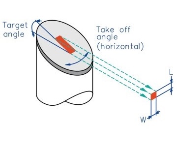
X-ray tubes with reflection target are benefiting from the so called "Goetze - principle". The optical length of the focal spot will be reduced with smaller target angles. In this way higher load can be positioned at the same focal spot. The termal focal spot can be calculated with the following table: The optical spot varies with different directions looking at the target. The table below shows the calculated optical focal spot size at different angles.
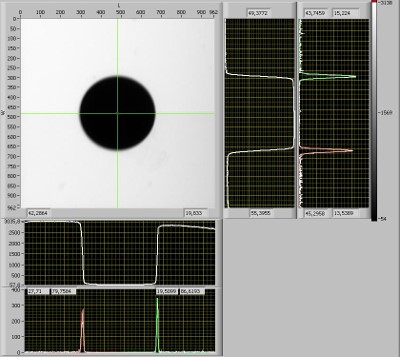
The measurement according to DIN EN 12543-2 gives a direct view on the focal spot by means of a pinehole camera. It is taken for focal spots larger than 100µm.
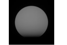
The method according to DIN EN 12543-5 is taken for small focal spots below 100µm. The focal spot size is calculated from the unsharpness of e.g. a tungsten ball.
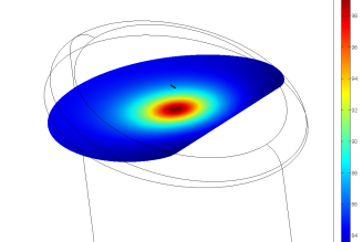
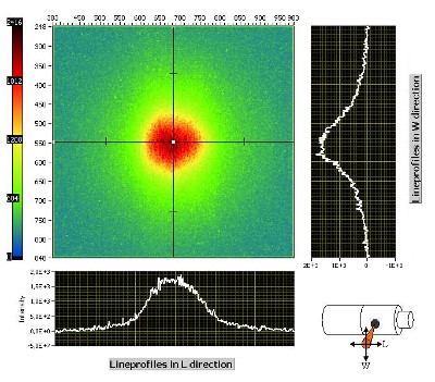
Intensity distribution on a CCD X-ray camera from a 12° target X-ray cone beam.
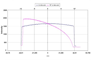
The intensity distribution is horizontally effected by the "distance to square law" and vertically additional by the heal effect.
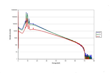
With smaller take off angles more soft X-rays will be absorbed.
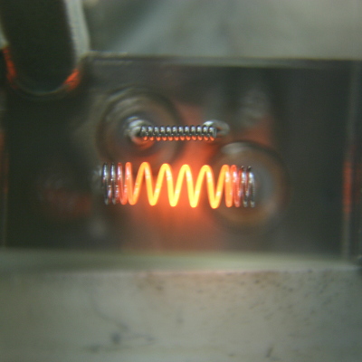
The electrical power of the filament in correlation to the diameter of the filament wire determinates the electronemission and the lifetime. So the current flow increases the temperature at the filament and hereby the electron emission. This effect is used to control the tube current (mA).
By reducing the filament current by 5 % only, the lifetime will be extended by 50 %.
The Soret effect and electromigration is based on a considerable temperature gradient longitudinally along the direction of the wire axis. The mass transport (of tungsten atoms) which occurs, produces a notched surface structure of the filament.
This results inevitably in a reduced cross section which can lead to a fracture under the influence of shock or vibration or pulsed working. 50 % filament lifetime reduction has to be calculated when working with a DC filament power supply.
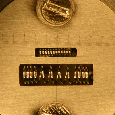
Some applications for X-ray tubes involve mechanical shock and vibration. The rtw filaments are subject to special annealing procedures during the manufacturing, for high mechanical stability and high resistance to shock and vibration. Shock and vibration has to be avoided anyway.
Switching the filament on and off will cause an alternation of the filament temperature, thus creating a series of phases of internal stress, which in turn reduces the lifetime, too.
rtw recommends to preheat the filament.
During ramping up modes the fi lament power supply may produce electrical overshots (short overvoltages and overcurrent). This shortens the lifetime.
Electrical tube over power or due to insufficient cooling, ions may be released. Their electric charge being opposite to that of electrons, causes them to move opposite to the direction of the accelerated electrons and hit the filament.